The Simulated Robot
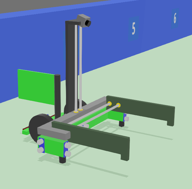
There is a pre-built robot used in the simulator. To allow this simulated robot to move around and sense its environment a set of motors and sensors have been connected as detailed below.
The simulator’s API is very similar to the real SR API described in the programming docs. The main differences are:
- the way that time is handled,
- the simulated arduino only offering the plain SR Firmware interactions, and
- the simulated robot not having the Brain Board LEDs.
Motors
Your robot has one motor board attached, the motor on the left wheel is connected to the “Motor 0” port, and the right wheel to “Motor 1”. These can be referenced with robot.motor_board.motors[0], and robot.motor_board.motors[1], respectively.
See the motor board programming docs for how to control these.
If you want to reference the motor board by its the part code, you can use the part code srABC1.
Servos
Your robot has one servo board attached, the jaws of the robot and the lifter are all controlled by servos.
| Servo | Location |
|---|---|
| 0 | Left Jaw |
| 1 | Right Jaw |
| 2 | Lifter |
Setting each servo to -1 fully opens the respective jaw, setting them to 1 fully closes them.
Setting the lifter to -1 fully lowers the lifter, setting it to 1 fully raises it.
You can access the servos with robot.servo_board.servos[N] where N is the number of the servo from the table above. Read more at the servo board programming docs.
If you want to reference the servo board by its the part code, you can use the part code srXYZ2.
Arduino
Your robot has an arduino board, with one microswitch and six distance sensors, attached to the digital and analog pins respectively.
The simulated arduino behaves like one with the ordinary SR Firmware, the simulator doesn’t support any extended firmware or custom arduino firmware. Read below for details on the individual sensors.
Make sure you have set the correct pin_mode, depending on what device you’re using.
Microswitches
The rear of the robot has a wide bump sensor attached to a microswitch.
The microswitch is attached to digital pin 2:
| Pin | Location | Required Mode |
|---|---|---|
| 2 | Back | INPUT |
This is shown as a red coloured block on the robot. You can access the servo using robot.arduino.pins[2]. Make sure you set the pin mode to INPUT. The digital_read method will return a bool telling you whether the switch is currently being pressed. You can read more in the arduino programming docs page.
Distance Sensors
Analogous to ultrasound sensors, distance sensors allow you to retrieve the distance between your robot and an object. These are attached to analog pins A0-A5:
| Pin | Location | Required Mode |
|---|---|---|
| A0 | Front Left | INPUT |
| A1 | Front Right | INPUT |
| A2 | Left | INPUT |
| A3 | Right | INPUT |
| A4 | Front | INPUT |
| A5 | Back | INPUT |
These are shown as blue boards with silver transceivers on the robot. They can see in a narrow cone up to a maximum of about 2m away. Since these sensors rely on echoes being reflected back from objects, if the angle of incidence between the sensor’s pulse and the contacted surface exceeds 22.5 degrees then the sensor will be unable to detect the object.
You can access the ultrasound sensors using robot.arduino.pins[AX], where ‘AX’ is between A0 and A5. Make sure you set the pin mode to INPUT. The analog_read method will return a voltage (0-5V) proportional to the distance. You can read more in the arduino programming docs page.
reading = R.arduino.pins[A5].analog_read()
# convert reading from volts to meters
measurement = reading / (5/2)
print(f"Rear ultrasound distance {measurement:.2f} meters")
LEDs
Your robot has two LEDs mounted in clearly visible points on the robot. The LEDs are attached to digital pins 3-4:
| Pin | Location | Required Mode |
|---|---|---|
| 3 | Red (lower) | OUTPUT |
| 4 | Green (upper) | OUTPUT |
You can access the LEDs using robot.arduino.pins[3] or robot.arduino.pins[4]. For the red or green LED, respectively. Make sure you set the pin mode to OUTPUT. You can read more in the arduino programming docs page.
Using the digital_write method, you can set these to True (On) or False (Off).
Vision
The simulated robot has a camera which provides position and orientation information about other objects within the simulation. This simulates the system of fiducial markers which the physical robot’s camera can detect.
You can access the camera with robot.camera. The simulated vision system matches the physical robot’s vision API, so please use the vision programming docs page as a reference. There are a few small differences between the simulator and the physical kit which are noted on that page.
If you want to see for yourself what the robot camera can see, you can enable an overlay of the camera’s view by right clicking on the robot then going to Overlays → Camera Devices → Show ‘camera’ overlay.
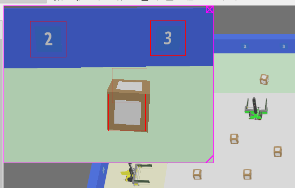
The overlay shows the simulated objects which can be seen from the camera’s perspective as well as red outlines around any markers which Webots’ vision system can identify.
You can move the preview around within Webots window, or double-click on it to pop it out to its own window.
As Webots has full awareness of the whole of the simulation, there may be markers highlighted in the preview which your real robot’s camera would not be able to see. In order to make the simulation closer to your real robot, the simulator API filters out these markers.
Consequently: there may be markers highlighted in the preview which the API does not return.