Power Board
 The Power Board distributes power to the SR kit from the battery.
It provides eight general-purpose power outputs, with port L2 reserved for powering the Brain Board.
You can control the state of these outputs from the Power Board API.
The Power Board distributes power to the SR kit from the battery.
It provides eight general-purpose power outputs, with port L2 reserved for powering the Brain Board.
You can control the state of these outputs from the Power Board API.
It also holds the internal On|Off switch for the whole robot as well as the Start button which is used to start your robot code running.
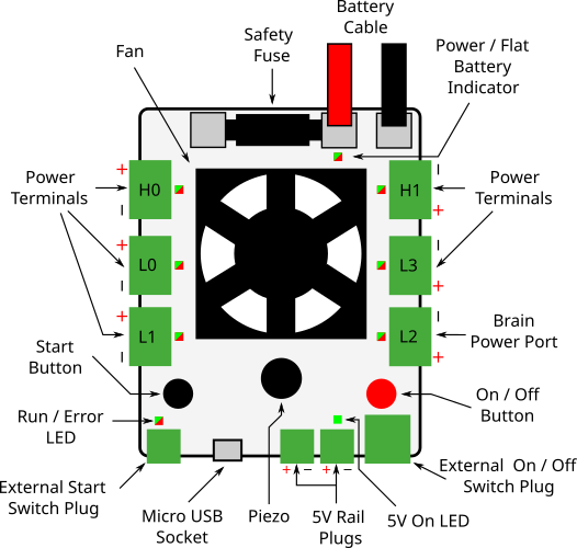
Board Diagram
Connectors
There are six power output connectors on the board, labelled L0–L3, H0, and H1. These are enabled when your robot code is started, supply around 11.1V (±15%) and will turn off when your robot code finishes. These may be referred to as 12V ports elsewhere in the docs. They should be used to connect to the motor and servo board power inputs. The “H” connectors will supply more current than the “L” connectors.
The 5V connectors can be used to connect low-current devices that take 5V inputs.
There is also a Micro USB B connector which should be used to connect the Brain Board for control of the power board.
Finally, there are connectors for external Start and On|Off switches. You may connect any push-to-make latching switch for the On|Off button, or a push-to-make button for the start button.
Indicators
| LED | Meaning | Initial power-up state |
|---|---|---|
| PWR|FLAT | Green when powered Flashing red and green when the battery is low |
Green |
| 5V | Green when 5V is being supplied | Green |
| H0-1, L0-3 | Green when the output is on 1 Red when the output’s current limit is reached |
Off |
| RUN|ERROR | Orange on power-up, or USB reset Flashing green when ready to run Solid green when running or booting |
Orange |
On power-up, the Power Board will emit a beep.
If the Power Board starts beeping (and all the outputs turn off) then this means that the whole board’s current limit has been triggered.
Controls
| Control | Use |
|---|---|
| ON|OFF | Turns the power board on, when used in conjunction with an external switch |
| START | Starts your program |
Fan
The power board has a fan to keep the board cool when it is under high load. The fan will only begin to spin when the board gets hot.
Case Dimensions
The case measures 83×99×24mm. Don’t forget that the cables will stick out.
Specification
| Parameter | Value |
|---|---|
| Main battery fuse current | 40A |
| Overall current limit2 | 30A |
| High current outputs (H0-1) | 20A |
| Low current outputs (L0-3) | 10A |
| Motor rail output voltage (nominal) | 11.1V ± 15% |
| Maximum output current per 5V channel | 1A |
Designs
You can access the schematics and source code of the firmware for the power board in the following places. You do not need this information to use the board but it may be of interest to some people.